Flow measurement for dense-phase conveying
Continuous solids mass flow measurement in dense-stream conveying and high levels of throughput
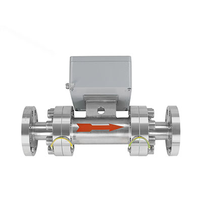
Designed to measure solid flows during pneumatic dense phase transport.
The sensor measures density and speed.
- no wear thanks to the ceramic inner pipe
Also available as a high pressure version, up to 110 bar
- Features & Benefits
- Main applications
- Technical Specifications
- Technical Data
- Mounting Installation
- Downloads
- Reliable flow metering in pneumatic dense-stream
- Unlimited throughput volumes can be measured
- Optionally pressure-resistant up to 25 bar
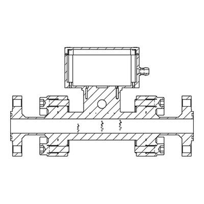
- Installation creates no obstacle in the profile, hence no dead spots in which residue can form
- Measurement independent of the flow speed of the material
- Simple retrofitting
- Maintenance-free
- Contactless measuring procedure (no mechanics)
- Materials: Powder or granules in pneumatic dense-stream transport in steel industry
| Technical Specifications | |
|---|---|
| Material to measure | Dust and powders |
| Working principle | Electromagnetic |
| Process pressure | 25 bar, optional up to 110 bar |
| Process temperature | Up to +120°C |
| Mounting | Flange build-in |
| Type of Conveying | Pneumatic densphase |
| Flow rates | No limit |
| Pipe diameter | Max. DN 150mm |
| ATEX rating | Category 3, Cat. 1 applied |
| Output | 4…20mA, Modbus, Profibus |
| Sensor Technical Data | |
|---|---|
| Housing | Steel St 52, powder-coated (optional Stainless steel 1.4571 DN 10…125 mm (bigger diameters on demand) Flange EN 1092-1 |
| Inner pipe | Ceramic |
| Protection category | IP65 |
| Ambient temperature Mediums temperature |
Sensor electronic: 0 … +60 °C Sensor pipe: 0 …+80 °C (higher temperatures as option) |
| Working pressure | Max. 25 bar, optional 64 bar |
| Working frequency | 88 kHz |
| Weight | Depending on the nominal diameter |
| Velocity range | 1…10 m/s |
| Dimension | Ø DN + 150 mm, L 500 mm |
| Accuracy | ± 2…5 % in calibrated range |
| Transmitter Technical Data | ||||
|---|---|---|---|---|
| Transmitter (DIN Rail) | Transmitter (field housing) | |||
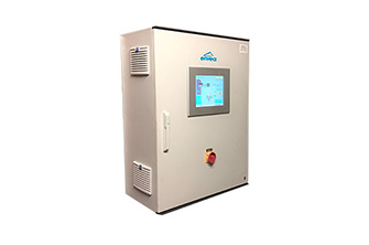
| Power supply | 24 V DC ±10 % | 110 / 230 V AC 50 Hz (optional 24 V DC) |
||
| Power consumption | 20 W / 24 VA | |||
| Protection type | IP 40 to EN 60 529 | IP 65 to EN 60 529/10.91 | ||
| Ambient operating temperature | -10 … +45 °C | |||
| Dimensions (W x H x D) | 23 x 90 x 118 mm | 258 x 237 x 174 mm | ||
| Weight | Approx. 172 g | Approx. 2.5 kg | ||
| Connection terminals cable cross-section |
0.2-2.5 mm2 [AWG 24-14] | |||
| Current output | 1 x 4 … 20 mA (0 … 20 mA), load < 500 Ω |
3 x 4 … 20 mA (0 … 20 mA), load < 500 Ω |
||
| Interface | RS 485 (ModBus RTU) / USB | |||
| Pulse output | Open collector – max. 30 V, 20 mA | |||
| Relay contact | Max. rated load: 250 V AC Max. peak current: 6 A Max. rated load 230 V AC: 250 VA Max. breaking capacity DC1: 3/110/220 V: 3/0.35/0.2 A Min. switching load: 500 mW (10 V / 5 mA) |
|||
| Data backup | Flash memory | |||
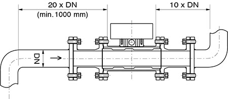
| In pneumatic dense-stream conveying , the installation point is specified in accordance with the conveyed inlet and outlet paths.
The assembly of the measuring tube at the specified installation point takes place using a flange installation. Measuring tubes can be supplied in standard form in nominal widths of up to 150 mm with flange connections in accordance with DIN 2576. |
 |
