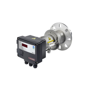
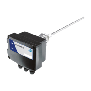
- Features & Benefits
- Main applications
- Technical Specifications
- Technical Data
- Mounting Installation
- Downloads
- Simple and uncomplicated retrofitting
- Reliable fill level and limit level detection
- Signalling through relay switching
- Detection through all non-conductive walls
- With process adapter up to 220 °C and 20 bar pressure possible
- With ceramic mounting up to 1,000 °C possible
- Absolutely insensitive to material cakings
- Can be used up to a profile of 25 m (larger profiles on request)
- Compact device – no separate electronics
- Can also be supplied in short housing with separate electronics
- Limestone
- Tiling
- Waste incineration
- Cement
- Building materials
| Technical Specifications | |
|---|---|
| Material to measure | Dust, powders or granulates |
| Working principle | Microwave |
| Silo diameter/ detection range | 25m |
| Process pressure | Max. 20 bar |
| Process temperature | Up to 1000°C |
| Mounting | 1 1/2 ” threat connection |
| Place to measure | Silos, containers, chutes, pipelines, transition points |
| Output | Relay |
- The microwave barrier is a contactless measuring procedure
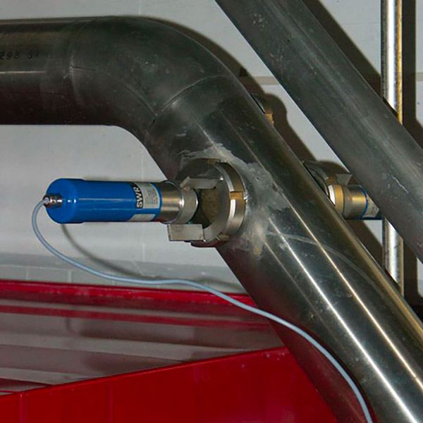
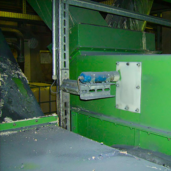
- Can be installed in containers, pipelines, shafts or free-fall sections
- Range is 0.1 … 25 m
- If container walls, housings or pipelines are not metal, it is possible to measure from the outside
- Can also be used under difficult conditions such as high operating temperatures and pressures with the help of a process-adapter
- The use of microwaves also ensures a high level of insensitivity to any caking on the sensor window
| Sensor Technical Data | |
|---|---|
| Material | Housing: Stainless steel 1.4571 Sensor-Isolation: POM |
| Protective system | IP 65 |
| Using in Ex-zones | Outside pipe: Cat. 3 GD Inside pipe: Cat. 1/3 G and Cat. 1/3 D (only with process adapter) |
| Dimension ProGap 2.0-BS |
Housing: L 103 mm / Ø 52 mm Thread: L 30 mm / Ø G11/2 |
| Dimension ProGap 2.0-BS Ex |
Dimension ProGap 2.0-BS Ex |
| Process temperature | -20 … + 80 °C -20 …+220 °C (with process adapter) max. 1000 °C (with ceramic flange) |
| Ambient temperature | -20…+60 °C |
| Working pressure | max. 1 bar max. 20 bar (with process adapter) |
| Detection range: Leveln | 0.1 … 25 m (> 25 m on request) |
| Detection range: Flow | 0.1 … 12,5 m (> 12,5 m on request) |
| Power supply | 24 V DC powered by DIN Rail electronic |
| Power consumption | approx. 1.8 VA |
| Current consumption | max. 100 mA |
| Measuring frequency | K-Band 24.125 GHz (± 100 MHz) |
| Transmitting powe | max. 5 mW |
| Cable gland | M16 (Ø 5-10 mm) |
| Weight ProGap 2.0-BS | approx. 560 g |
| Weight ProGap 2.0-BS Ex | Transmitter: 1.1 kg Receiver: 1.1 kg |
| DIN Rail electronic Technical Data | |
|---|---|
| Power supply | 24 V DC ± 10 % |
| Power consumption | 3.5 W |
| Current consumption | 120 mA at 24 V |
| Relay contact | Max. rated load: 250 V AC Max. peak current: 6 A Max. rated load 230 V AC: 250 VA Max. breaking capacity DC1: 3/110/220 V: 3/0.35/0.2 A Min. switching load: 500 mW (10 V/5 mA) |
| Fall-delay time | 0.25 …5 s (continuously adjustable) |
| Weight | approx. 172 g |
| Protective system | IP 40 |
| Technical Data | ||||
|---|---|---|---|---|
| Pressure adapter | Temperature adapter | Food adapter | High temperature adapter | |
| Material | Stainless steel 1.4571, POM diaphragm |
Stainless steel 1.4571, Tecapeek diaphragm |
Stainless steel 1.4571, Tecapeek GF30 diaphragm |
Steel Ceramic diaphragm |
| Temperature | -20…+80 °C | Max. +220 °C | Max. +220 °C | Max. 1000 °C |
| Pressure | Max. 20 bar | Max. 20 bar | Max. 20 bar | Max. 40 bar |
| Thread | G1/2 inch on both sides | G1/2 inch on both sides | G1/2 inch on both sides | G1/2 inch on sensor sides |
| Wrench width | 55 mm | 55 mm | 55 mm | 17 mm |
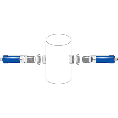
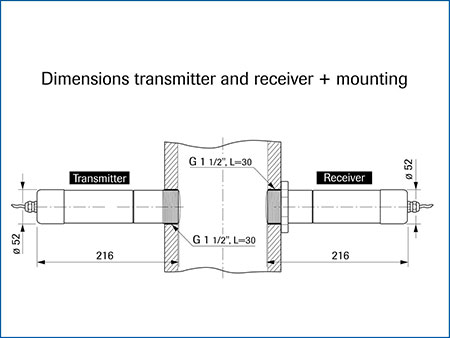
| The transmitter and receiver are installed by screwing into a G 1 ½” threaded connection. The device can be installed at any installation height. It is important that the transmitter and receiver have the same installation height. The adjustment takes place with the help of a counter-threaded connection. A display of the signal intensity facilitates the adjustment. The connection to the power supply takes place on the transmitter and the receiver. The switch output is made available on the receiver. No additional analysis unit is necessary. |
 |
