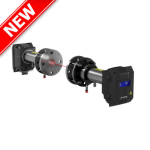
- Features & Benefits
- Main applications
- Technical Specifications
- Technical Data
- Mounting Installation
- Downloads
- Supply a trending information of pulverization
- Measures changes in particle size for instance to detect screen breaks
- Paddy is insensitive against contaminations and works without bypass
- Uses state-of-the-art microwave technology in combination with intelligent evaluation software
- Can be installed in free-fall pipes downstream from screening or grinding systems
- Fast detection of coarse particles, for as little as 10 % of the mass flow
- Cement
- Food
- Wood
| Technical Specifications | |
|---|---|
| Material to measure | Dust, powders or granulates, not agglomerated |
| Process pressure | 1 bar, optional 10 bar |
| Process temperature | Max. 80°C |
| Mounting | Via process connection, after baffle plate or Venturi |
| Type of Conveying | Pneumatic leanphase, vertical freefall |
| ATEX rating | Category 1/2 |
| Output | 4…20mA Trend, Modbus, Profibus |
- Fast detection of coarse particles, for as little as 10 % of the mass flow
- Uses state-of-the-art microwave technology in combination with intelligent evaluation software
- Can be installed in free-fall pipes downstream from screening or grinding systems
- Possibility of trend showing for grain size
- Special freefall section include baffle plates needed
- Consists of two sensors (measurement and reference)
| Sensor Technical Data | |
|---|---|
| Measurement principle | Microwave |
| Measurement range | Particle sizes up to 10 mm – larger sizes on request |
| Housing material | Stainless steel 1.4571 |
| Protection type | IP 65, dust explosion zone 20 or gas explosion zone 1 (optional) |
| Ambient operating temperature | Sensor tip: -20 … +80 °C Optional: -20 … +200 °C Sensor element: 0 … +60 °C |
| Max. operating pressure | 1 bar |
| Operating frequency | K band 24.125 GHz, ±100 MHz |
| Transmission power | Max. 5 mW |
| Weight | 1.3 kg |
| Dimensions | Ø 60, Ø 20, L 271 mm |
| Transmitter Technical Data | ||||
|---|---|---|---|---|
| Transmitter (DIN Rail) | Transmitter (field housing) | |||
| Power supply | 24 V DC ±10 % | 110 / 230 V AC 50 Hz (optional 24 V DC) |
||
| Power consumption | 20 W / 24 VA | |||
| Protection type | IP 40 to EN 60 529 | IP 65 to EN 60 529/10.91 | ||
| Ambient operating temperature | -10 … +45 °C | |||
| Dimensions (W x H x D) | 23 x 90 x 118 mm | 258 x 237 x 174 mm | ||
| Weight | Approx. 172 g | Approx. 2.5 kg | ||
| Connection terminals cable cross-section |
0.2-2.5 mm2 [AWG 24-14] | |||
| Current output | 1 x 4 … 20 mA (0 … 20 mA), load < 500 Ω |
3 x 4 … 20 mA (0 … 20 mA), load < 500 Ω |
||
| Interface | RS 485 (ModBus RTU) / USB | |||
| Pulse output | Open collector – max. 30 V, 20 mA | |||
| Relay contact | Max. rated load: 250 V AC Max. peak current: 6 A Max. rated load 230 V AC: 250 VA Max. breaking capacity DC1: 3/110/220 V: 3/0.35/0.2 A Min. switching load: 500 mW (10 V / 5 mA) |
|||
| Data backup | Flash memory | |||
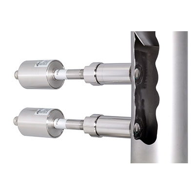
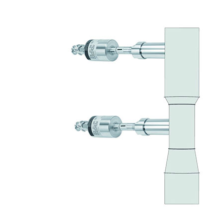
| At the selected installation site two sensor sockets are welded at the required distance. Thereafter, a 20 mm borehole is drilled through sensor socket and through the tube wall. The sensor will be adapted to the wall thickness, inserted and fixed with the help of the union nut. | 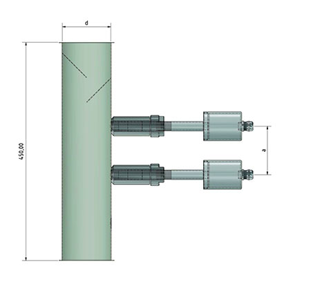 |
 |
